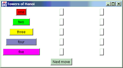
Towers of Hanoi starting position
|
Figure 1 Towers of Hanoi starting position |
|
This article discusses the recursive solution to this puzzle; and then refactors the algorithm to demonstrate an application of the "gang of four" Interpreter design pattern.
But how can we move the four smallest disks to peg B? If we knew how to move the three smallest disks to peg C, then we could easily move disk four to peg B, and repeat the hidden handshake capable of moving the three smallest disks back on top of disk four.
Moving those three disks is still too hard. Lets decompose that requirement into: move the two smallest disks to peg B, move disk three to peg C, and move the two smallest disks back on top. But moving two disks is still beyond our capacity to solve unassisted. So well decompose that task yet one more time: move disk one to peg C, move disk two to peg B, and then reposition disk one back on top of disk two.
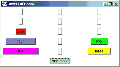
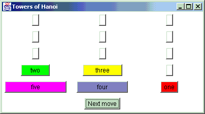
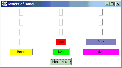
In summary, if the original goal is to move five disks to peg C, then the sub-goals are to move: four disks to peg B, three disks to peg C, two disks to peg B, one disk to peg C. Once we have achieved each lower level sub-goal, we retrace our steps upward and outward until the original goal is achieved. Figure 2 shows us to be one move away from having three disks on peg C. Figure 3 is two moves away from having four disks positioned on peg B. Figure 4 has the two most buried disks where they belong, and it is now a simple matter to move: disk three to peg C, disk one to peg A, disk two to peg C, and disk one to peg C.
|
Figure 2 Almost ready to move disk four to peg B |
 |
|
Figure 3 Almost ready to move disk five to peg C |
 |
|
Figure 4 Disks four and five in position, only 4 moves remain |
 |
Notice that the pegs find themselves playing different roles with respect to the current decomposition. These roles are: source (aka from), destination (or to), and auxiliary (spare).
Listing 1
The classical recursive solution
void move( int number, int from, int to, int spare, List instructions ) {
  if (number == 1) {
    instructions.add( new LeafMove(from,to) );
    return;
  }
  move( number-1, from, spare, to, instructions );
  instructions.add( new LeafMove( from, to ) );
  move( number-1, spare, to, from, instructions );
}
The list of LeafMove objects are created in the domain layer,
and then used in the presentation layer. [The complete code for the
domain layer is here. The presentation
layer is here.]
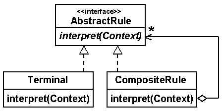
The Interpreter pattern (reference 2) prescribes: define a domain language as a simple grammar, represent the grammar rules as a network of objects, and feed problem statements to the resulting interpretation machine. Grammars are usually hierarchical in structure. They start with an abstract root construct, and proceed through possibly many levels of specialization, until finally only terminals (or literals) are derived. This problem structure is perfect for the Composite design pattern (reference 3). In fact, comparing the reference design class diagrams for the Interpreter and Composite patterns in figures 5 and 6, it is apparent that the Interpreter pattern is a thin veneer on top of the Composite pattern.
|
Figure 5 Interpreter design class diagram |
 |
|
Figure 6 Composite design class diagram |
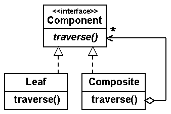 |
The Interpreter design starts with an AbstractRule base type. This interface specifies the abstract recursive method interpret(Context). Context is the data structure that encapsulates the input being recursively consumed, and, the output being produced. Each grammar rule is mapped to a class derived from AbstractRule. If the construct references nothing but literals, then the corresponding class functions in the role of Terminal. If the construct references other grammar constructs, then its class plays the role of CompositeRule This class represents old-fashioned recursion, and the Terminal class represents boundary condition(s) that designate the end of each recursive thread.
Listing 2
A grammar for the Interpreter pattern
solution ::= CompositeMove
CompositeMove ::= LeafMove | CompositeMove LeafMove CompositeMove
LeafMove ::= source destination
source ::= 'A' | 'B' | 'C'
destination ::= 'A' | 'B' | 'C'
To implement the grammar, the first order of business is instantiating the Interpreter hierarchy. It will be composed of a CompositeMove object that corresponds to each application of recursion in the original solution. To get it started, we could use the following statement
CompositeMove solution = new CompositeMove( size, 0, 2, 1 );Size can be any number; but for our problem, we'll assume it is five. The second argument is the source peg, the third argument is the destination peg, and the last is the auxiliary peg.
The contructor of the CompositeMove class will look very much like the move()
method in the recursive solution (see listing 3). Once the set-up is complete,
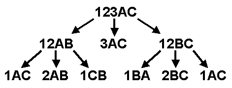
well have an object hierarchy whose top looks something like figure 7, and a
portion of whose bottom looks like figure 8. The top of figure 7 should be
read: to move disks one through five from peg A to peg C, first move disks one
through four from A to B, then move disk five from A to C, and finally move the
previous four disks from B to C. The decomposition proceeds until nothing but
leaf moves (moving a single disk) are achieved.
Listing 3
Creating CompositeMove objects
class CompositeMove implements ComponentMove {
  private ArrayList children = new ArrayList();
  public CompositeMove( int size, int from, int to, int aux ) {
    if (size == 1) {
      children.add( new LeafMove(from,to) );
      return;
    }
    children.add( new CompositeMove( size-1, from, aux, to ) );
    children.add( new LeafMove( from, to ) );
    children.add( new CompositeMove( size-1, aux, to, from ) );
  }
|
Figure 7 The "top" of the hierarchical solution |
 |
|
Figure 8 A portion of the "bottom" of the solution |
 |
Now that the cast of objects is in place, all that remains is to recursively traverse them as specified by the Composite pattern. The code is shown in listing 4. As with the previous recursive solution, the list of LeafMove objects are collected here in the domain layer, and then displayed in the presentation layer. The CompositeMove objects do not directly contribute anything to the solution; their purpose is strictly to provide structure for the LeafMove objects that encapsulate the concrete steps of the ultimate solution.
Notice the correlation between the Interpreter patterns interpret(Context)
method, and our recurse(List) method. [The complete code for this
alternate domain layer is here.]
Listing 4
Recursive traversal of a Composite pattern
interface ComponentMove {
  void recurse( List l );
}
class CompositeMove implements ComponentMove {
  public void recurse( List l ) {
    for (int i=0; i < children.size(); i++)
      ((ComponentMove)children.get(i)).recurse( l );
} }
class LeafMove implements ComponentMove {
  public void recurse( List l )  {
    l.add( this );
} }
An algorithmic choice like the humble function is a significant tool of the trade. It can encapsulate a unit of functionality that needs to be reused many times over. It can transform input into output. It can even put itself on hold while requesting the services of another function, or even itself.
An object-oriented approach takes these benefits and adds the ability to meld functions and data structures into one cohesive unit. It allows us to colocate both state and behavior. It provides a higher form of indirection; and all problems in computing science can be solved with one more level of indirection.
The Interpreter design pattern documents how to map a simple language (represented by a grammar) to an object-oriented class hierarchy. Once this is implemented, then problems in the domain can be modeled with sentences in the language, and these sentences can be applied to the interpretation engine to mechanically produce results.
2. Gamma, Erich, et al, Design Patterns, Addison-Wesley, 1995, pp243-255
3. Gamma, Erich, et al, Design Patterns, Addison-Wesley, 1995, pp163-173